The first in a series of three reports from events exploring underground construction, held by Architecture Today in partnership with waterproofing specialist RIW
Subterranean City 1: Waterproofing Complex Basements
Alex Massingham, UK Technical Lead at RIW, explains the bespoke nature of waterproofing basement structures
Subterranean City 2: Expanding Institutions
In recent projects the British Museum, the V&A and UCL have dug deep to make the most of their campuses
Subterranean City 3: Dealing with Neighbours
Encountering restrictions both below and above ground at the Francis Crick Institute and the House in a Garden

Alex Massingham, UK Technical Lead at RIW, explains the bespoke nature of waterproofing basement structures
Any below-ground structure should be designed to provide protection against water ingress, and there are several types of waterproofing design for use in basement construction.
• Type A – barrier protection – applies a continuous barrier membrane around the structure.
• Type B – integral – forms a structure which is non-porous.
• Type C – drained – relies on limiting water ingress through the structure, provides a drainage void around the inside face of the structure and removes water ingress through a pump.
Types A and B are designed to halt water ingress, but all junctions and details in these systems must be anticipated and correctly designed before construction work begins on site. Therefore existing or complex structures may benefit from additional types of waterproofing. In particular, Type A protection is considered effective where protection against gas ingress (radon, methane, carbon dioxide) is also required. Type C protection intercepts any seepage through the structure. It is generally installed after the structure has been formed and therefore offers greater flexibility and the capacity to compensate for unforeseen detailing or junctions as they are uncovered during construction, such as at movement joints, or where new structure meets existing.

Type A: barrier protection
BS8102 identifies combined protection as providing two independent waterproofing systems in a below-ground structure where the risk of water ingress is ‘high’ or the result of water ingress is ‘catastrophic’. The primary waterproofing system is the first system the water may try to pass through and is located towards the back of the structure generally. Consideration should be given to how much access the contractor needs to install this first line of defence, and the practicality of repairing this waterproofing if required after handover or during the construction phase.
The secondary waterproofing system starts working if any water bypasses the first system. As recommended in BS8102 ease of access to the system and the available method of repair should be considered eg an underground car park with no finishes is very different from a hotel lobby with expensive finishes where there are considerable costs associated with down-time.

Type B: integral protection
Basements can be defined as simple or complex. In a simple basement an extended site boundary permits access around the full perimeter of the structure, providing full control of surrounding areas and over the design of the substrate, drainage and structure. Complex basements include extending existing basements, building against a boundary wall, partial retention of existing below-ground structure, basement infill sites, underpinning or propping existing structure, and deep excavations.

Type C: drained protection
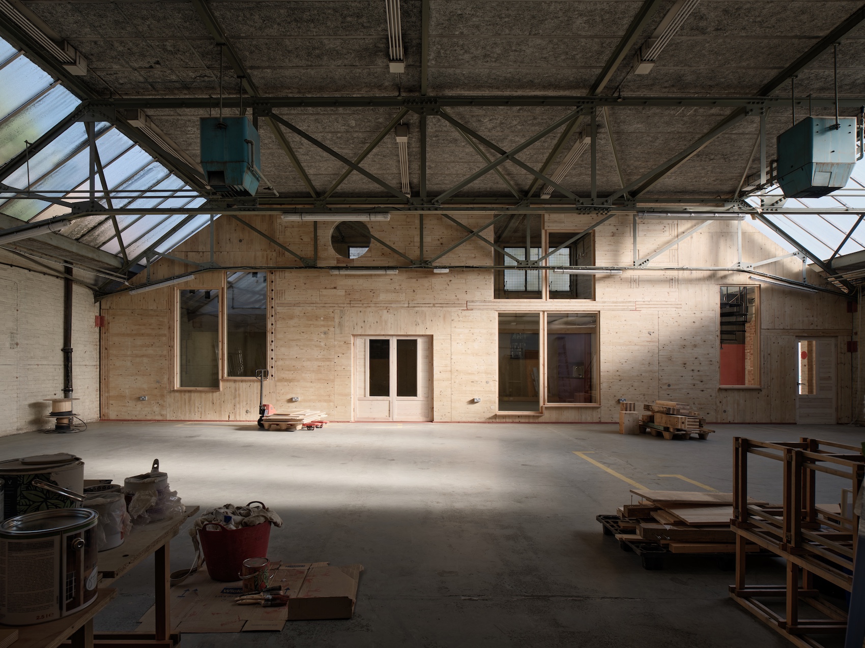
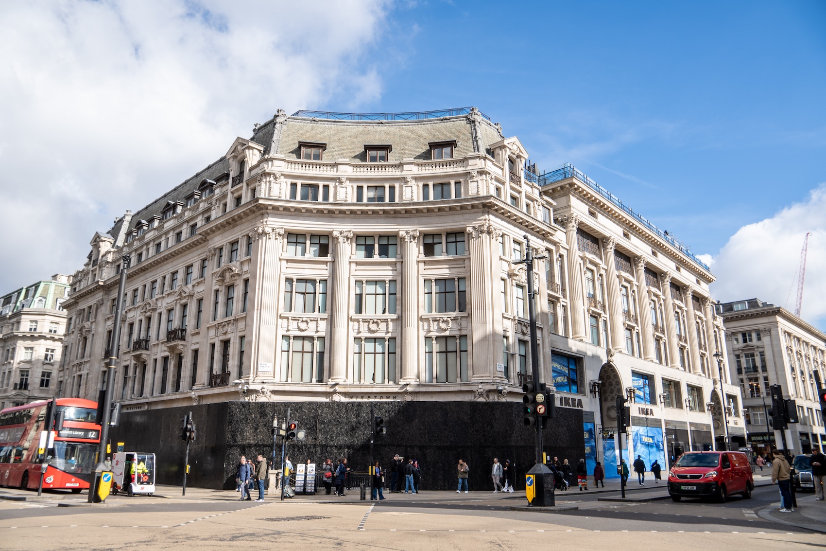
At The Copyright Building in London’s Fitzrovia, designed by Piercy & Co, RIW acted as the waterproofing design specialist, coordinating with project delivery and design teams and providing project-specific technical design advice to ensure that all regulatory requirements were met, and that the system was correctly designed and installed on site.
The basement space was to provide a mixture of plant and storage areas in an infill site where it could not be effectively drained from the external face. East and west elevations were constrained by streets, where excavation was taken out to boundary line. The existing basement wall was retained and propped to prevent the roadway from falling in but the presence of propping made both construction sequence and waterproofing more complex, and increased the number of joints in the structure.

The Copyright Building
Props were cast into slab and wall so there were greater penetrations through the waterproofing. North and south elevations were built tight against neighbouring properties. Neighbouring property foundation depths were not entirely understood and eventually resulted in some required level changes in the basement slab depth.
The broad concept for this project was to provide combined protection using Type A external barrier membrane, which with the concrete box would limit the vast majority of water ingress, plus Type C internally applied drained protection as a final line of defence which could compensate for any unforeseen detailing or workmanship issues which might have affected the performance of the Type A barrier.

Type A waterproofing at the Copyright Building: tanking using RIW Structureseal barrier membrane
The neighbouring structure was used as a back shutter, against which the new retaining walls were cast. The Type A barrier was pre-applied to the existing structure, steel reinforcement was installed and the basement walls were subsequently cast. There was therefore no available access to retrospectively inspect or repair any defects in the Type A barrier.
A Type A barrier membrane was applied beneath the whole of the basement floor slab. The step in the basement slab created no additional considerations for the first line of waterproofing but created more complexities for the Type C Drained protection, so this required more detailing input at an early stage, before the casting of the slab. Finishes and screeds were placed directly against the studded drainage membrane.

Detail of the junction at the boundary wall, showing how the structure and waterproofing had to squeeze in around the neighbouring structure and the boundary line
Generally the drainage sumps are located at the lowest point in the basement and close to the eventual discharge point. The sump and pump are the most important part of the system, a twin pumping station is recommended including battery back-up. Regular maintenance of the system is essential. It should feature a high-level alarm and a wireless router connection to communicate with the pump manufacturer via wi-fi.

Type C drained protection to the inside face of the Copyright Building
The structures of new-build deep basement projects have evolved to become quite formulaic in their design, but while they might look similar the chosen waterproofing approach can vary significantly depending on different factors. Two deep basement projects in central London, both designed to Grade 3, illustrate this point. One Crown Place, designed by KPF, is an urban redevelopment comprising commercial space on the lower floors and two residential towers – so consideration had to be given to the house builder warranty requirements – and two storeys of basement. Designed by Allies & Morrison, 100 Bishopsgate is prime office space in the heart of the City and houses a three-storey basement.

Secant pile wall at One Crown Place prior to Type A barrier installation
At One Crown Place Type A waterproofing was combined with Type B. The structure was a secant pile wall with a pile-bearing raft slab and a concrete lining wall cast in front of the secant pile wall. The capping beam was propped at ground level until all the below-ground structure had been cast. RIW Structureseal external barrier membrane was applied to the face of the secant pile wall and beneath the basement slab, effectively lining the whole below-ground concrete box. Pile heads and other penetrations through the membrane were dressed with a liquid-applied membrane to ensure continuity in the waterproofing barrier. The below ground concrete box was cast using watertight concrete, so any leaks into the basement structure would require local access to the inner concrete surface for a resin injection repair.

Type A barrier installation below the basement slab at One Crown Place
BS8102 recognises that a secant pile wall on its own can provide an integral barrier (Type B protection) so this project actually provided Type B (secant), Type A (barrier membrane) and Type B again (watertight concrete box).
Here the package contractor, responsible for the detailed design of the waterproofing, had to demonstrate that it was able to provide two systems of waterproofing from a single source to show clear accountability for the design and installation of the waterproofing.
As is commonplace, the secant pile wall was installed by a different contractor and so from an ownership/accountability point of view it was important that two additional lines of defence were proposed, installed and warrantied from a single source. The housebuilder warranty programme also required that all waterproofing products were BBA-certified for independent verification of their performance and suitability.

Secant pile connections to capping beam and slabs at One Crown Place
This waterproofing design approach, of Type A & B, will not be damaged nor affected by subsequent change of use so gave the client freedom to fix into the concrete, to move internal lining walls, and to customise the below-ground space as desired.
Hypothetically, had this been a site where protection against hazardous ground gases was required, this method of protection would have worked well as a gas-resistant external barrier. This approach also works well for fast track construction, making it possible to leave the concrete box as the finish if so desired.

Blockwork lining wall in front of vertical Type C protection at 100 Bishopsgate, with hearth-like apertures for rodding points every 12 metres
At 100 Bishopsgate RIW’s Cavity Drain profiled sheet was proposed to the vertical secant pile wall face while watertight concrete provided the horizontal protection at the B2 slab level. One challenge was the thickness of the B2 slab, because watertight concrete is more expensive than conventional concrete. The B2 slab was therefore cast as a monolithic, split application, with the lower part of the slab cast in untreated concrete and the upper top surface of the slab (generally 300mm thick) in watertight concrete. The watertight concrete is applied wet-on-wet to the untreated concrete so that the concrete behaves as a single piece of structure.

100 Bishopsgate: B1 wall/slab interface detail
The B1 slab put a break in the the Type C Cavity Drain as it runs down the face of the secant pile wall, so watertight concrete was also used for the first section of B1 slab, where it intersects the secant pile wall. The edges of this slab had to be cast with holes at regular intervals to allow water collected in the Cavity Drain system at B1 level to drain down to B2 level, where it was collected and removed from the building by mechanical pump. As with all cavity drain systems, it is necessary to provide access to clear potential blockages in the drainage system.

100 Bishopsgate: B2 wall/slab interface detail
The role of RIW is to provide a high level of technical consultancy, coordinating project delivery and design teams and delivering a robust, cost effective strategy in accordance with regulatory requirements, through early engagement, where possible, together with attendance at design meetings, creating project-specific detailing and construction drawings and supplying on-site support.
Different waterproofing systems may be needed to establish clear ownership and accountability, to meet NHBC, LABC & other warranty requirements, for client flexibility and change of use, as well as dealing with different floor-to wall junctions, and taking into consideration end use, the presence of ground gases and fixings penetrating the structure.